" 이러한 Shader에 의한 Shading 처리의 가장 커다란 특징은 아무리 카메라를 Zoom In해도 똑같은 느낌으로 재 계산 처리해 준다는 점이다. Texture Mapping의 경우, 해당 Bitmap Image의 크기와 관련하여 카메라를 Zoom In 할 경우, Pixel이 거칠게 나타나 인위적인 느낌이 든다. 하지만 Shading의 가장 큰 단점은 시간이 오래 걸린다는 점이다. Texture의 경우, 해당 Mapping Source Image의 크기에 비례하므로 작업자가 해당 Object의 크기와 중요성에 입각해 Bitmap이미지의 크기와 세밀함을 차별화 할 수 있지만, Shading의 경우 전적으로 프로그램 내부에서의 계산에 의존하게 되므로 작업자는 Object에 걸맞은 질감과 시간을 잘 파악해서 선택적으로 사용해야 한다. "
포인트 추가 : 해당 위치에 마우스 클릭 포인트 선택 : 해당 포인트를 마우스 클릭 포인트 선택 해제 : 모델 이외의 지점 클릭 포인트 제거 : alt 클릭 시작점 보기: ctrl 포인트 클릭 포인트 이동: move 모드에서
여러개의 포인트 이동 : draw사이즈 up 포인트 크기 : scale모드에서 커넥션 라인 지우기 : 중간에 새 포인트를 추가한 다음, 지운다. geometry를 topology로 바꿀때 : shift 클릭 unerease geometry : shift alt 클릭, 또는 paint된 영역을 shift클릭
Quick Start 1 polymesh 모델을 임포트(primitive는 사용X) 2 edit mode로 3 툴에서 지스피어 선택 4 tool>rigging>select 임포트한 모델 선택 5 tool>topology>edit topology on
Editing existing topology1 모델 임포트 2 툴에서 zsphere선택 3 모델을 clone 4 모델의 레벨을 낮춰줄 것. 5 tool>rigging>projection on으로 6 tool>topology>select topo 7 tool>topoloty>edit topology
그 외 관련사항 메모 *topology는 선택된 서브툴에 대해서만 작용하고, 완성된 오브젝트가 되지 않는다. 현재까지는, 일단 obj익스포트 한 다음, 다시 import해서 add하는 방법밖에. *지스피어로 뼈대를 만들고, topology 메쉬로 감쌀 수 있다. 지스피어 뼈대를 Rig로 사용할 수 있음. *mesh extratction처럼, 옷이나 갑옷 등을 만들 때 활용할 수 있음. geometry에 대한 컨트롤을 제공한다는 장점이 있음. *topology rigging - 기술적으로 결점이 있으나 일단 간단한 transpose 가능. --> 좀 더 자세한 사항 볼 것.
번역을 신뢰하지 말 것. 반드시 원문을 참고할 것! -by KCN 개인적으로 공부한 것을 정리해 나가는 것이고, 여러번 고심한 번역도 절대 아님.
(32비트FP에 관련된 내용중 직접적으로 필요한 내용은 대부분 디스플레이스먼트 맵에 관련되어있다. 채널당 32bit의 정보를 사용한다는 것인데, 머드박스와 지브러시에 방식차이가 조금씩 있는 것 같기도 하다. 머드박스의 경우 알파값을 바꾸지 않고도 바로 정확하게 렌더링 걸렸는데, 지브러시 MD로 뽑은 경우는 그렇지 않았다. 지브러시의 경우 ADE 옵션에 대해서 좀 찾아봐야 할 듯. (멘탈레이에서)
머드나 ZB나 둘 다 RGB파일에 용량도 비슷했지만, 렌더링 걸리는 게 다르다. MD에서 1개 채널로 뽑으면 나중에 .map으로 변환이 안 되었다. 그리고, 채널당 바이트 수가 16비트에서 32비트로 올라가면, 파일 용량도 2배 늘어난다. 렌더타임은 32비트가 약간 더 많이 걸리지만, 심하게 늘어나지는 않았음.
머드박스의 경우, 32비트 노말맵이 에러가 나서 뽑히지 않았다. 24비트로 세팅하고, 뽑은 경우, 최종 파일이 48비트인 걸로 봐서, 32비트는 아직 지원이 안 되는 걸지도??)
(영문 위키대백과 ,전반적인 내용)
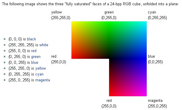
24비트 트루컬러는 red를 8bit, blue를 8bit, green를 8bit로 표현한다. 각각의 컬러에는 256(2의8승) 단계가 있고, 그러므로 이를 조합하여 총 16,777,216 (256*256*256)가지의 컬러를 표현할 수 있다.
24bit 컬러 이미지에 추가로 그 외의 8bit 데이타(예를 들어 alpha나 z 또는 범프)를 가지고 있는 경우를 '32bit'라고 하는 것은 잘못 지칭한 것이다. 실제 컬러 데이타에 24비트 이상을 사용하는 시스템도 있지만, 대부분은 30bit implementation이다. (2bit를 끼워 넣어서 각 채널이 똑같이 10bit를 가지고 있도록 하는 방식)
24비트 이상으로 올라가면서, 몇몇 시스템들은 nonlinear한 방식으로, 데이터를 저장할 여분의 공간을 사용하고 있다. 보통, dynamic range이미지로, 디스플레이 되는 것 이상의 데이타를 저장하는 형태이다. 데이타를 저장하기 위해, white and black의 값을 넘어선 floating point number를 사용한다. ->HDRI ->이렇게 함으로써 같은 color space에서 왜곡이 덜 되면서도, 정확한 태양관의 강도나 deep shadow를 정확하게 표현할 수 있다.
24-bit truecolor uses 8 bits to represent red, 8 bits to represent blue and 8 bits to represent green. 28 = 256 levels of each of these three colors can therefore be combined to give a total of 16,777,216 mixed colors (256 × 256 × 256). "32-bit color" is generally a misnomer in regard to display color depth. While actual 32-bit color at ten to eleven bits per channel produces 4,294,967,296 distinct colors, the term "32-bit color" is most often a misuse referring to 24-bit color images with an additional eight bits of non-color data (I.E.: alpha, Z or bump data), or sometimes even to plain 24-bit data. Systems using more than 24 bits in a 32-bit pixel for actual color data exist, but most of them opt for a 30-bit implementation with two bits of padding so that they can have an even 10 bits of color for each channel. As bit depths climb above twenty four, some systems are using the extra room to store data nonlinearly, with the most common form being the storage of more data than can be displayed all at once, as in extended dynamic range imaging, including high dynamic range imaging (HDRI). Floating point numbers are used to describe numbers in excess of 'full' white and black. This allows an image to describe accurately the intensity of the sun and deep shadows in the same color space for less distortion after intensive editing.
(about 32bit from English Wiki)
(지브러시, 디스플레이스먼트 관련) <channel resolution> 각각의 channel은 resolution을 가지고 있고, 이는 얼마나 많이 강도의 변화를 표현할 수 있는지에 대한 척도이다. 더 높은 resolution일 수록 더 정확하게 시각적 정보를 저장할 수 있다. channel resolution은 각각의 픽셀의 해당 channel에 얼마나 많은 데이타가 저장되어 있느냐에 따라 달라진다. 각 포인트에 저장되는 비트수로 표현된다.
32비트 포맷은 보통 'floating point'포맷에 저장된다.
32비트 포맷에 저장했을 때 얻을 수 있는 잇점은, export해야 할 경우, alpha depth factor(alpha 팔레트안 하단의 슬라이더) 값이 이미 정해져 있어서, 같은 디스플레이스먼드 맵을 수정한 것을 계속 익스포트 할 때 그 값을 변경할 필요가 없다는 것이다. 또한 다른 디스플레이스먼트 맵을 만들었을 때에도, alpha depth factor를 조절할 필요가 없다.
Each channel has an associated resolution, which is a measure of how many gradations of intensity it can represent. The higher the resolution, the more accurately visual information can be stored. The resolution of a channel is determined by how much data is stored, for each image pixel, in that channel, and this is normally expressed by the number of bits (binary digits) stored at each point.
32 bit formats are usually stored in what is called a ‘floating-point’ format.
The most likely advantage you’ll see when using the 32 export format is that, once a satisfactory alpha depth factor has been determined for your export needs (set by the Alpha Depth Factor slider in the Alpha palette), you will not need to change it when subsequently exporting new versions of the same displacement map.
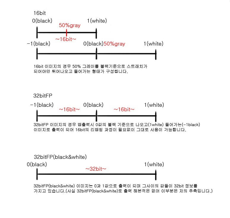
(area 포럼) -16비트 맵은 gray level로, 거리를 가지고 상대적으로 normalize한 것이다. -32비트맵은 로우모델과 하이 모델 사이의 world space상의 정확한 거리를 베이크한다. -하이 모델이 로우 모델의 surface보다 안쪽에 위치하는 경우에, 이를 nagative value로 베이크 되는데, 이런 경우 보통의 이미지 뷰어로는 디스플레이가 되지 않는다.
A 32 bit map records the exact world space distances between the low res and high res mesh. high res mesh is inside the low res mesh than the measured distance will have a negative value. These values can not be displayed on the monitor as is.
렌더링의 측면에서, world space unit을 사용하는 것은, 렌더 타임이라는 점에서 normalize된 맵에 비해, 디스플레이스먼트의 높낮이를 조정이 쉽다. 디스플레이스먼트 쉐이더는 보통 1로 세팅되어있고, 맵의 픽셀 값에 따라 높이 정보를 바로 읽어올 수 있다. 이렇게 추출된 디스플레이스먼트 맵은 높이에 대해 추측할 필요가 없으며, 스컬럽팅한 모델과 같이 보인다. world space unit을 사용하므로, 오브젝트의 크기를 바꾸어도 깨지지 않는다.
On the render side of things, using worldSpace units makes it very easy to control the displacement height at render time compared to normalized maps. The shader displacement height is normally set to 1 and it will read the height information right from the pixel values of the map. There is no guessing involved about the height of your extracted displacement maps and it will look just like your highRes sculpt. As the maps are in worldSpace units, scaling your object will break this relationship. If you have to scale your object from the initial extraction size, you need to multiply the height by your scale factor. For example, if you lowRes got scaled by 3 after extracting the maps, you need to change the displacement height from 1 to 3 as well.
zenus`s BLOG에서 가져옴. 16bit 와 32bit의 차이점
blog.naver.com/bukjang <- 원 출처는 이곳이라고 하는데, 원문을 찾을 수가 없음...;
*Tool>Geometry>Suv setting before dividing the mesh
*if/when you have two uv regions is go to tool > subtool > grp split. and physically split your mesh into two parts (based off of your uv regoins).
your normal map will then be generated correctly.
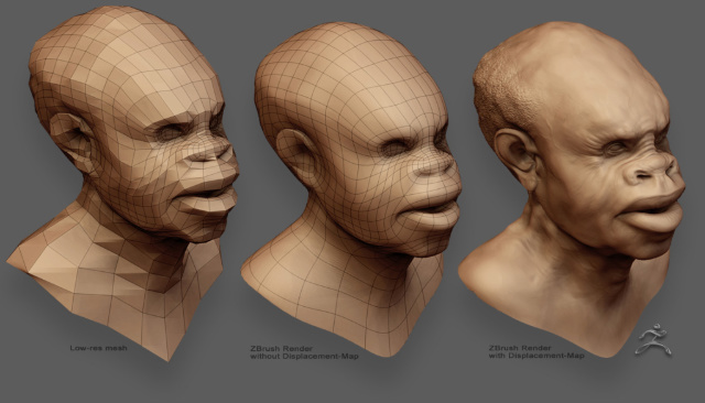
*The workflow a maquette and scan it into ZBrush-->by generating a Ztool using the topology tools, you can recreate the mesh with a uniform polygon density --> major changes to the form using a lower subdivision level-->sculpting the details *it is important not to work with a high subdivision level too early. *seams in the normal map can be removed using BodyPaint.
*Maya is limited to 1.5 million polygons.
*Although there are couple of ways to apply normal maps in Max, the Projection modifier using a cage is the best method.
*To view a normal map within the viewports apply the rendered normal map to the Bump channel.
*Illuminate Lab’s Turtle, a plug-in for Maya. It can create normal maps by transferring one surface to another.
*use normal maps when it makes sense. For example, it makes no sense to apply a 512 by 512 normal map to a model that only has 2400 polygons. At this resolution, the normal maps will make no difference in the final render. The key is to find the sweet spot that optimizes the CPU/GPU loading.
* Visible seams is another tricky spot for normal maps. To see the seams, have a developer write a shader that shows a preview of the normal tangents. This makes it easy to see the seam problems. To fix seams, paint over them with a 127 red brush with the Clone tool in Photoshop. A more aggressive solution is to break down the geometry, flip the normals along the seam and add a weight value. You can also improve the final results by using a 4X anisiotropic filter. It is also important to keep all seams straight in UV space.
Hide 된 포인트가 있으면 경고창이 뜬다. 모든 메쉬를 visible로 두고 세이브 하도록.
세이브된 파일은 start up list에 뜬다.
단축키 지정할 수 있음.
Hotkey 'B'
최상위 서브툴과 선택된 서브툴의 visibility를 토글
Hotkey 'N'
커서아래의 서브툴의 이름을 보여주면서 그 서브툴을 select할지 여부를 옵션으로 고른다.
Pop up Interface
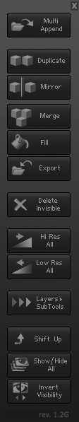
---MultiAppend---
Ztool을 서브툴에 append
obj파일을 불러아서 append.
---Duplicate---
선택된 서브툴을 duplicate 하여 리스트의 맨 아래에 추가해줌.
Hd Geometry는 복사되지 않음.
---Mirror---
선택된 서브툴을 Duplicate 한 다음 mirror. 메쉬에 add 할 것인지 새 서브툴로 append 할 것이지를 옵션으로 선택. 가장 높은 sdiv레벨에서 mirror하면, merge 되거나 append 된 서브툴의 낮은 레벨 정보는 사라진다.
---Merge---
서브툴을 visible로 둔 상태에서 merge할 것. 나머지 서브툴들을 보존하거나 없앨지 옵션으로 선택. 'Preserve existing Polygroups'에 체크하면, Merge한 메쉬는 각각의 서브툴에 맞추어 polygroup으로 바뀐다. 서브툴의 현재 sdiv레벨은 사용하고 있는 것으로 다른 레벨이나 any HD Geometry는 사라진다.
---Fill---
Visible 상태인 서브툴을 컬러나 material로 채워준다.
---Export---
visible상태인 서브툴을 Obj나 DXF파일로 익스포트
---Delete InVisible---
visible상태가 아닌 서브툴을 지움. Undo되지 않으니 주의할 것.
---HiRes All---
모든 서브툴을 가장 높은 레벨로 세팅
---LowRes All---
모든 서브툴을 가장 낮은 레벨로 세팅
---Layers>SubTools---
현재의 3d layer를 visible상태의 서브툴에 카피???
* Copies the current 3D Layer status to the visible subtools.
* Layer intensity slider adjusted and visibility set.
* Creates new layers as necessary or switches off extra ones.
* Useful if you want to transfer in poses using layers or quickly show the Art Director alternative treatments.
---Shift Up---
visible상태의 서브툴을 리스트의 맨 위에 그룹으로 생성해줌
---Version Number panel---
맨 아래의 버전 넘버 부분을 클릭하면 단축키 지정을 바꿀 수 있다.
임시 버튼은 ZPlugin의 서브 메뉴에 생기며, 버튼을 Ctrl + 클릭하여 단축키를 지정한다. 이 버튼들은 단축키 지정에만 쓰이며, Ctrl 키를 누르지 않고 그냥 클릭하면 버튼을 없앨수 있다. 이 버튼들을 닫으려면 버전 넘버 부분을 다시 클릭한다.
NOTES
- 선택된 서브툴은 눈모양 아이콘과는 관계없이 항상 visible 상태로 변한다.
- 몇몇 툴 – 예를 들면 Merge – 는 zspheres나 parametric primitives와는 작동하지 않을 수 있다.
-서브툴이 merge 되었을 때, 결과물의 폴리곤 개수가 500,000개를 초과한 경우 경고 메시지가 뜬다. 계속 진행할 것이지는 사용자가 선택
- MultiAppend 를 사용할 경우, 기존에 서브툴이 없거나, 맨 처음에 사용하는 툴로 default Polymesh3D star ztool이 선택되 있으면, OBJ파일을 append하는 것이 작동하지 않을 수 있다. (지브러시가 파일을 import 하는 방식 때문). 이 경우 Polymesh3D tool에서 클론을 사용해 보시오.
위 방법이 작동하지 않는경우 내컴퓨터->속성->고급->환경변수 시스템변수에서 Path선택 ->편집->줄 끝으로 가서 ;C:\Program Files\Autodesk\Maya8.5\bin -이라고 추가해준다
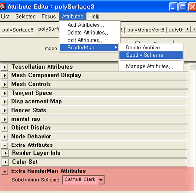
zbrush에서 디스맵 뽑기 방법1. tool>diplacement 설정 dpsubpix - 글로벌 서브디비전 <-> adptive 대체로 속도가 좀 더 빠르다 adptive에 문제가 있을 경우, 예를들면 가끔 pinch를사용했을 때 dp가 더 잘나오기도 둘 다를 체크해보시오 smoothuv사용하지 않아도 큰 차이가 없다는 의견.
생성된 디스맵을 alpha>de option에서, DE-HBEK-EAEAEA-R16 -> R16(rgb16bit), status on, vertical filp yes export current
방법2. Z-brush2, multi displacement 옵션 UDIM: leave at default.
Initial File Index: leave at default.
Max Map Size: I find that 2048 works fine, but you can go up to 8K
Map Size Adjust: change this to 0.
DpSubPix: leave at 0, will use adaptive instead.
Border: can leave at 8, as this will actually overpaint UV seams. In my tests, it actually does an ok job of overpainting if your UV's arent that great.
-> Click the export options button in the multi-displacement 2 menu and make sure that D32 is off (as well as every other setting) and turn on R32.
* Paste this quickcode into the quickcode box for R32: